Since I want to focus on digital computation, I try to keep the electricity part as simple as possible while still teaching the basics needed to understand how digital logic gates are implemented. For this reason, I discuss CMOS transistors. What's nice about CMOS is that there is no need to introduce any other electrical component (like resistors or capacitors) to understand how to build logic gates in CMOS.
In this simplified presentation, voltage is all that matters and we can basically ignore the details of electric current. All you need to know is that electrons at Ground potential (0V) represent '0's and electrons at Power potential (usually +5V) represent '1's.
Cards & Yarn
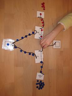
When I was first teaching this topic (a few years ago), I started by using laminated paper images of transistors that I connected with yarn (for the wires) using paper clips. The cards & yarn are used to layout a simple CMOS circuit and then the students have '0' and '1' markers flow through the circuit.
These were very low cost and worked acceptably well for the lesson.
 |
| Transistor cards connected with yarn |
- More difficult/time-consuming to build. In most cases, I ended up building the circuit and showing the students how it worked because it was a bit messy to get everything connected properly.
- Difficult to 'reset'. Once you were finished with one set of inputs, you need to remove all the markers to reset things for the next set of inputs. And you can't just sweep the markers away because that will mess up the connections. This made the activity less suitable for students to work on independently.
- Gets confusing when the yarn overlaps. With the NAND and NOR circuits, the yarn 'wires' overlap which can make it confusing to follow. This can be mitigated by using different colored yarn, but it's still a problem that needs to be dealt with.
- Weak against wind attacks. The materials are light, so a slight breeze from an open window can be enough to mess up your carefully constructed circuit. They can also be messed up easily by a student accidentally brushing their sleeve across the work area.
Laser-cut tiles
To address these problems with the paper & yarn approach, I started experimenting with using laser-cut wooden tiles. I drew a set of prototype tiles using Inkscape and had them fabricated either locally at Metrix Create:Space or online using Ponoko.
Each tile is roughly 1.5" on a side, and there are tabs on all sides so they can interlock like puzzle pieces. They need to be cut from opaque material, so I chose 1/8" inch wood stock.
Here are the basic tiles I created:
| Power |  |
 |
Ground |
| Input/Output |  |
||
| nMOS Transistor |  |
 |
pMOS Transistor |
| Straight wire |  |
 |
Bent wire |
| "T" connection |  |
 |
Wire crossover |
The tiles ended up looking very nice and the students find them much more satisfying to work with. I can now give each student (or pair of students) a set of tiles and a circuit to create and they will work independently.
Here are some pictures from the most recent batch of tiles (these ones arrived from Ponoko):
 |
| 9x9 tiles in package |
 |
| Removing the upper wax protective sheet |
 |
| Close-up of nMOS & pMOS transistor tiles |
 |
| Removing tiles from the sticky wax backing paper |
After removing the tiles, I group them into student packets that contain the tiles needed to construct the logic gates I cover in class.
 |
| Starting to build... |
Here are a few pictures of the students working with the tiles in class.
 |
| Building an inverter |
 |
| Constructing a NAND gate |
 |
| Another student's NAND gate |
Sadly, the one downside to these materials is their cost. The paper & yarn version costs practically nothing, while having the tiles custom laser-cut can be rather expensive. This is especially true if you want to have enough materials for an entire class.
What about using real transistors?
Another option that I considered was to use actual transistors in class. However, I opted against it because:
- Students can't see what's going on. The transistor itself is a black lump of plastic with 3 wires coming out and the electrons are not visible in the wires. While this might not be a serious problem for older students, I wanted the materials to be appropriate for younger students as well.
- Adding LEDs requires more knowledge of electronics. If we want to add LEDs to make the input/output values visible, then we need to pay more attention to electrical current and also add resistors. This would not only complicate the lesson, but it would also introduce material that would be a distraction from the primary goal of understanding digital logic.
- I'll be covering electronics later anyway. Later in the school year, we'll be working with Arduinos and lighting up LEDs. No need to rush this material now.
Making available
I'll be releasing these materials in the near future: image files for laser-cutting (so you can cut your own tiles if you want) and worksheets for using the tiles in class. I'll also have the original transistor cards released as well since that's the low-cost way to try out these lessons.
No comments:
Post a Comment